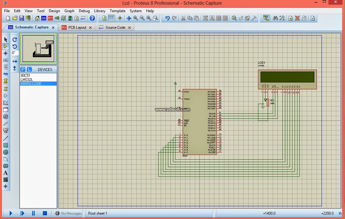
Hello friends, today we are going to write code for LCD display using keil compiler and simulating using proteus software
1 Clear display screen
2 Return Home
4 Decrement Cursor
6 Increment Cursor
8 Display 'OFF' & Cursor 'OFF'
0c Display 'ON' & Cursor 'OFF'
E/F Display 'ON' & Cursor 'Blinking'
80 Force cursor to beginning of 1st line
c0 Force cursor to beginning of 2nd line
38 Two line 5x7 matrix

sbit rs=P2^0;
sbit rw=P2^1;
sbit en=P2^2;
void delay(int ms)
{
int i,j;
for(i=0;i<=ms;i++)
for(j=0;j<=1000;j++);
}
void lcdcmd( char a)
{
P1=a;
rs=0;
rw=0;
en=1;
delay(1);
en=0;
}
void lcddata(char a)
{
P1=a;
rs=1;
rw=0;
en=1;
delay(1);
en=0;
}
void main()
{
int i;
char st[30]="welcome to sympos";
char ch;
lcdcmd(0x38);
lcdcmd(0x0c);
lcdcmd(0x06);
lcdcmd(0x01);
while(1)
{
for(i=0;i<20;i++)
{
lcddata(st[i]);
}
ch=st[0];
for(i=0;i<=20;i++)
{
st[i]=st[i+1];
}
st[i-1]=ch;
st[i]='\0';
lcdcmd(0x80);
}
}
Explanation of the code:
RS: RS stands for read switch, When RS=0, the command register will be read and when RS=1, the message signal will be read.
RW:RW stands for reading and writing operation, when RW=0,read operation will take place, when RW=1, write operation will take place.
EN: EN stands for enable signal, when EN=1, start condition is given for writing process and when EN=0, stop condition is given for reading process.
lcdcmd(0x38): It is used for switching on the cursor/display, ( it is used for function setting 8 bit).
lcdcmd(0x0C): It is used for cursor off, display on.
lcdcmd(0x01):It is used for clearing display.
lcdcmd(0x80): It is used for left shifting operation.
After the connecting all connections double click on 8051 and dump the hex file. Press run and observe the output. In the practical circuit we required frequency circuit.
LCD:-
Before going to software coding we must and should know about pin configuration of LCD display.Basically LCD have 16 pins is shown below,and each has a special purpose that is given in the table given below. VE is for adjusting contrast of display,thus we connect it to a ground through variable resistor. Pin 15 & 16 is used for adjusting LED brightness,pin 5 is used for read/write operation if input is 1 then it performs read operation & if input is 0 then it performs write operation, pin 4 for register select if input is 1 it clears LCD display & if input is 0 it displays data.Commands of LCD display:-
LCD contains some commands,they are
Code Command to LCD register1 Clear display screen
2 Return Home
4 Decrement Cursor
6 Increment Cursor
8 Display 'OFF' & Cursor 'OFF'
0c Display 'ON' & Cursor 'OFF'
E/F Display 'ON' & Cursor 'Blinking'
80 Force cursor to beginning of 1st line
c0 Force cursor to beginning of 2nd line
38 Two line 5x7 matrix
Pin Configuration:-

Software Coding:-(copy these total code in keil compiler)
#include<reg51.h>sbit rs=P2^0;
sbit rw=P2^1;
sbit en=P2^2;
void delay(int ms)
{
int i,j;
for(i=0;i<=ms;i++)
for(j=0;j<=1000;j++);
}
void lcdcmd( char a)
{
P1=a;
rs=0;
rw=0;
en=1;
delay(1);
en=0;
}
void lcddata(char a)
{
P1=a;
rs=1;
rw=0;
en=1;
delay(1);
en=0;
}
void main()
{
int i;
char st[30]="welcome to sympos";
char ch;
lcdcmd(0x38);
lcdcmd(0x0c);
lcdcmd(0x06);
lcdcmd(0x01);
while(1)
{
for(i=0;i<20;i++)
{
lcddata(st[i]);
}
ch=st[0];
for(i=0;i<=20;i++)
{
st[i]=st[i+1];
}
st[i-1]=ch;
st[i]='\0';
lcdcmd(0x80);
}
}
Explanation of the code:
RS: RS stands for read switch, When RS=0, the command register will be read and when RS=1, the message signal will be read.
RW:RW stands for reading and writing operation, when RW=0,read operation will take place, when RW=1, write operation will take place.
EN: EN stands for enable signal, when EN=1, start condition is given for writing process and when EN=0, stop condition is given for reading process.
lcdcmd(0x38): It is used for switching on the cursor/display, ( it is used for function setting 8 bit).
lcdcmd(0x0C): It is used for cursor off, display on.
lcdcmd(0x01):It is used for clearing display.
lcdcmd(0x80): It is used for left shifting operation.
Hardware Connection:-
All the connections are shown below.When ever we open a new project in proteus it will open 8051 Micro controller and we can take required components from physical components or devices and connect all as shown in Image.After the connecting all connections double click on 8051 and dump the hex file. Press run and observe the output. In the practical circuit we required frequency circuit.


No comments:
Post a Comment