Friday, 30 December 2016

LCD scrolling operation in proteus

Hello friends, today we are going to write code for LCD display using keil compiler and simulating using proteus software

LCD:-

       Before going to software coding we must and should know about pin configuration of LCD display.Basically LCD have 16 pins is shown below,and each has a special purpose that is given in  the table given below. VE is for adjusting contrast of display,thus  we connect it to a ground through variable resistor. Pin 15 & 16 is used for adjusting LED brightness,pin 5 is used for read/write operation if input is 1 then it performs read operation & if input is 0 then it performs write operation, pin 4 for register select if input is 1 it clears LCD display & if input is 0 it displays data.

Commands of LCD display:-

 LCD contains some commands,they are
                    Code                                 Command to LCD register
                       1                                        Clear display screen
                       2                                            Return Home
                       4                                         Decrement Cursor
                       6                                         Increment  Cursor
                       8                                  Display 'OFF' & Cursor 'OFF'
                      0c                                  Display 'ON' & Cursor 'OFF'
                     E/F                                 Display 'ON' & Cursor 'Blinking'
                      80                             Force cursor to beginning of 1st line
                      c0                             Force cursor to beginning of 2nd line
                      38                                       Two line 5x7 matrix

Pin Configuration:-


Software Coding:-(copy these total code in keil compiler)

#include<reg51.h>
sbit rs=P2^0;
sbit rw=P2^1;
sbit en=P2^2;

void delay(int ms)
{
 int i,j;
 for(i=0;i<=ms;i++)
  for(j=0;j<=1000;j++);
  }

void lcdcmd( char a)
{
   P1=a;
   rs=0;
   rw=0;
   en=1;
   delay(1);
   en=0;
 }

 void lcddata(char a)
{
   P1=a;
   rs=1;
   rw=0;
   en=1;
   delay(1);
   en=0;
 }

 void main()
 {
   int i;
  char st[30]="welcome to sympos";
  char ch;
  lcdcmd(0x38);
  lcdcmd(0x0c);
  lcdcmd(0x06);
  lcdcmd(0x01);
  while(1)
   {
      for(i=0;i<20;i++)
   {
             lcddata(st[i]);
   }
             ch=st[0];
      for(i=0;i<=20;i++)
  {
      st[i]=st[i+1];
  }
      st[i-1]=ch;
      st[i]='\0';
             lcdcmd(0x80);
 }
 }


Explanation of the code:

RS: RS stands for read switch, When RS=0, the command register will be read and when RS=1, the message signal will be read.
RW:RW stands for reading and writing operation, when RW=0,read operation will take place, when RW=1, write operation will take place.
EN: EN stands for enable signal, when EN=1, start condition is given for writing process and when EN=0, stop condition is given for reading process.
lcdcmd(0x38): It is used for switching on the cursor/display, ( it is used for function setting 8 bit).
lcdcmd(0x0C): It is used for cursor off,  display on.
lcdcmd(0x01):It is used for clearing display.
lcdcmd(0x80): It is used for left shifting operation.

Hardware Connection:-

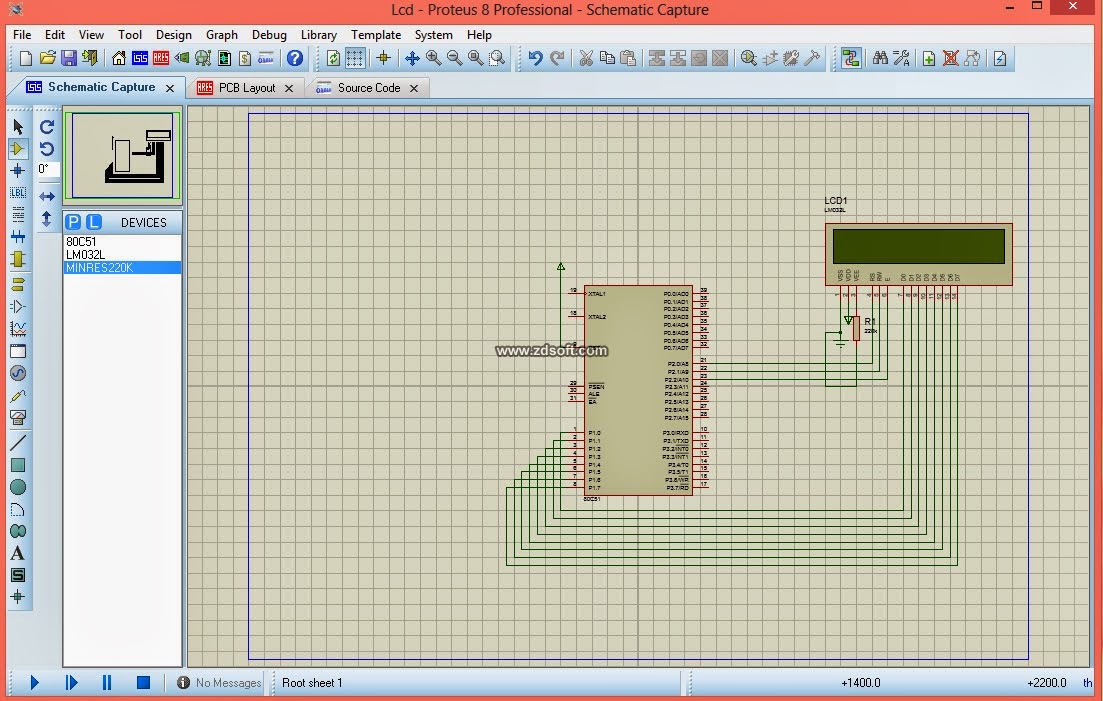
All the connections are shown below.When ever we open a new project in proteus it will open 8051 Micro controller and we can take required components from  physical components or devices and connect all as shown in Image.


              After the connecting all connections double click on 8051 and dump the hex file. Press run and observe the output. In the practical circuit we required frequency circuit.

Counting numbers from 0 to 99 using 7 segment display

Hi friends, In this writeup we will be explaining  how to count numbers from 0 to 99 by using seven segment display and will be showing it practically using proteus software. 


Hardware Implementation:- 

   The hardware components used  are 7 segment segment display and 8051 microcontroller. A seven segment display having a 8 diodes and one anode or cathode pin to display numbers from 0 to 9 and  there are two types common cathode and common anode. In common cathode we are connecting to the ground and in common anode we are connecting to the vcc. These is a seven segment display


The basic architecture of a seven segment display is shown below


The software implementation is mainly depends on the type of display chosen 


                  COMMON ANODE                                                 COMMON CATHODE


Hardware connection in proteus:


Software implementation:- (copy these code into keil uvision software and create HEX file)         

  #include<reg51.h>
   void delay(int a)
    {    unsigned int i,j;
          for(i=0;i<a;i++)
          for(j=0;j<=1000;j++);
       }
   void main()
      {
            char b[]={0x3F,0x06,0x5B,0x4F,0x66,0x6D,0x7D,0x07,0x7F,0x6F};
             int i,j;
             P2=0x00;
             P3=0x00;
             while(1)
                  {
                         for(i=0;i<=9;i++)
                                {
                                       P2=b[i];
                               for(j=0;j<=9;j++)
                                         {
                                                   P3=b[j];
                                                   delay(100);
                                          }
                                  }
                          }
 
               }


Thursday, 29 December 2016

Proteus diagram for glowing LED when switch is turned on

Hello friends, in the last post we have seen the coding part of the project by using keil software and now we will be using proteus software to test the given connection.

The following steps must be followed to implement the project succesfully:
1.Open proteus software.


2.Click component mode icon (which looks like diode symbol), click P symbol to open pick devices icon,and click the following devices

i)at89c51:


ii)switch:


iii)LED:


3. After opening all the devices, connect them as per the given diagram

4. Click terminal mode, and click ground and connect it to the switch

5.Play the given project by clicking the play icon.

6. The following diagram appears when the switch is on:


7. The following diagram appears when the switch is off:

Keil program for glowing led when switch is on

Hello friends, today we will be giving you details on how to glow led bulb when switch is turned on.

The following steps will be followed after opening keil software:

1.project ->  Î¼ vision project(mew vision),  create new project dialogue box appears and choose a      name to represent the program in the keil`
2.Now choose the microcontroller as "ATMEL",now choose the database as at89c51.
3.Now file -> new and start typing the following code.


CODE:

#include<reg51.h>
sbit SW=P1^5;
sbit LED=P2^5;
void main()
{
if(SW==0)
{
LED=1;
}
else
{
LED=0;
}
}

Explanation of the code:
i) #include<reg51.h> is a special header file to use keywords for 8051 microcontroller.
ii) sbit SW=P1^5 , in this statement a pin for switch is initialized which is connected to 5th pin in port 1.
iii) sbit LED=P2^5, in this statement a pin for LED is initialized which is connected to the 5th pin in port 2.
iv) The program is written in the main function where the logic is: if the switch is on,led is on and if the switch is off,led is off.


4.Save the file using .c(for eg:- group.c)
5.Source file -> add files to group source (right click) 
6. After adding the group source ,click target ->built target( it is used to create a complete project)
7 Target file(right click) -> options for target -> click output -> create hex file and then press ok to create the HEX file.
8.Now minimize the keil software and open  proteus to implement your project.


Wednesday, 28 December 2016

Arduino hc05 testing


int led = 13;
void setup()
{
  Serial.begin(9600);
  
  pinMode(led,OUTPUT);
  digitalWrite(led,LOW);
}
void loop()
{
 if(Serial.available())
 {
   String value = Serial.readStringUntil('\n');
   Serial.println(value);
   if(value == "on")
   {
     digitalWrite(led,HIGH);
   }
   else if(value == "off")
   {
     digitalWrite(led,LOW);
   }
  
 }
}


code for control arduino by voice from your phone:


int led = 13;
void setup()
{
  Serial.begin(9600);
  
  pinMode(led,OUTPUT);
  digitalWrite(led,LOW);
}
void loop()
{
 if(Serial.available())
 {
   String value = Serial.readStringUntil('\n');
   Serial.println(value);
   if(value == "*hello#")
   {
     digitalWrite(led,HIGH);
   }
   else if(value == "*1#") 
   {
     digitalWrite(led,LOW);
   }
  
 }
}

Tuesday, 27 December 2016

Smart door locking system using arduino

Hello friends, today i will be posting details on how to control DC motor using arduino and bluetooth which can be used for door locking systems.The components required are as follows:

1.Arduino:
2.Bluetooth module:


3.L293D IC


4.DC motor


5.Jumper wires


The list of components in a single diagram are as follows:


The schematics are given as follows:


*Make sure you remove the connections from hc05 bluetooth module before uploading the given program.


CODE:

/*
 * Control DC motor with Smartphone via bluetooth
 * created by Rui Santos, http://randomnerdtutorials.com
*/
int motorPin1 = 3; // pin 2 on L293D IC
int motorPin2 = 4; // pin 7 on L293D IC
int enablePin = 5; // pin 1 on L293D IC
int state;
int flag=0;        //makes sure that the serial only prints once the state
 void setup() {
    // sets the pins as outputs:
    pinMode(motorPin1, OUTPUT);
    pinMode(motorPin2, OUTPUT);
    pinMode(enablePin, OUTPUT);
    // sets enablePin high so that motor can turn on:
    digitalWrite(enablePin, HIGH);
    // initialize serial communication at 9600 bits per second:
    Serial.begin(9600);
}
 void loop() {
    //if some date is sent, reads it and saves in state
    if(Serial.available() > 0){     
      state = Serial.read();   
      flag=0;
    }   
    // if the state is '0' the DC motor will turn off
    if (state == '0') {
        digitalWrite(motorPin1, LOW); // set pin 2 on L293D low
        digitalWrite(motorPin2, LOW); // set pin 7 on L293D low
        if(flag == 0){
          Serial.println("Motor: off");
          flag=1;
        }
    }
    // if the state is '1' the motor will turn right
    else if (state == '1') {
        digitalWrite(motorPin1, LOW); // set pin 2 on L293D low
        digitalWrite(motorPin2, HIGH); // set pin 7 on L293D high
        if(flag == 0){
          Serial.println("Motor: right");
          flag=1;
        }
    }
    // if the state is '2' the motor will turn left
    else if (state == '2') {
        digitalWrite(motorPin1, HIGH); // set pin 2 on L293D high
        digitalWrite(motorPin2, LOW); // set pin 7 on L293D low
        if(flag == 0){
          Serial.println("Motor: left");
          flag=1;
        }
    }
}

 After uploading the following program in arduino, open sympos app and type the following message:

  • ‘0’ – Turns off the DC motor
  • ‘1’ – DC motor rotates to right
  • ‘2’ – DC motor rotates to left